
A Novel Channel Measurement Dataset for Wi-Fi Networks
On this page, you can find a dataset with Wi-Fi channel measurements, which can be used for developing new angle of arrival estimation algorithms and comparing existing ones. The key idea of our dataset is that it contains comprehensive information from both time and frequency domains, therefore it will be useful for comparing algorithms, requiring different types of information. The whole dataset and additional data for calibration can be found at
https://drive.google.com/drive/folders/1tpz8-aGJbrQVJbMz5FhNxO34dTheFokn?usp=sharing.
The link will become active right after publication of our paper “FIND: an SDR-based Tool for Fine Indoor Localization” on IEEE INFOCOM 2021 Demo, where this dataset will be introduced.
In case of using our dataset, please cite it as stated here.
FIND description
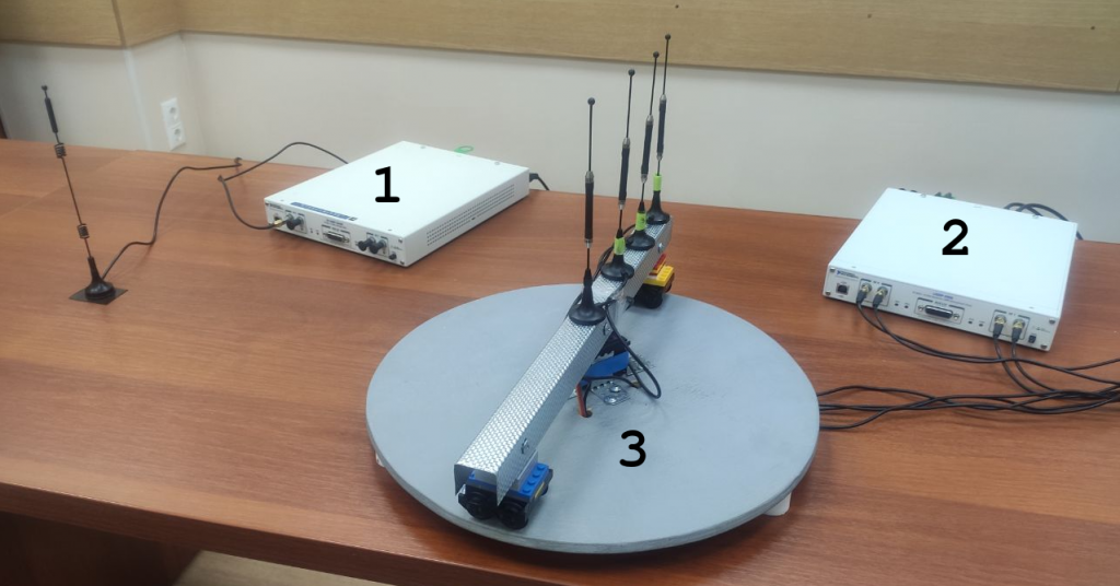
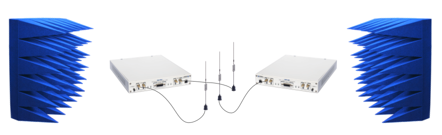
1 – transmitter, NI USRP-2945
2 – receiver, NI USRP-2955
3 – rotating platform with an antenna array
We use FIND (the tool for Fine INDoor localization) for gathering data. This tool is based on NI USRP-2955 and contains four antennas, forming a uniform linear array placed on a rotating platform. The separation between antennas is 6.25cm. Our device is capable of capturing real 802.11ac frames in an 80 MHz band, but at 2.4GHz instead of 5GHz, because the amplifiers of the channels RX 0 RF 0 and RX 1 RF 0 of the receiver are defective at 5GHz. It retrieves from such frames CSI (Channel State Information) from all 242 subcarriers of VHT-LTF field and time-domain IQ samples of the Legacy preamble and VHT preamble. We use NI USRP-2945 as a transmitter.
Experiments in a classroom
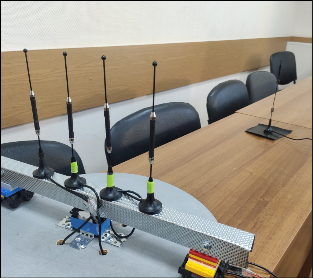
We gather our dataset as follows. First, we place the receiver and the transmitter in a random position in a classroom, then our platform is rotated at a defined angle, where the receiver captures 30 frames. After that the antenna array is rotated to the next angle. We define these angles from 0 to 180 in increments of 5. In each position, we repeat this process 10 times and then move our testbed to another position in space.
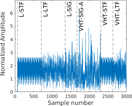
We extract CSI and time-domain IQ samples from each such frame. They are placed in the “classroom/position_N/repeat_K/angle_A” directory, where N is position number, K is repeat number in this position, A is the real angle of arrival, therefore our dataset has a hierarchical structure. File “csi.mat” in this directory contains matrix “csi” with shape 242x4x30, where 4 is channels number, 242 is subcarriers number, 30 is frame numbers, while file “samples.mat” contains matrix “samples” with shape 2880x4x30, where the only difference is that 2880 is a number of time-domain samples. These time-domain samples are: 640 samples of L-STF, 640 samples of L-LTF, 320 samples of L-SIG, 640 samples of VHT-SIG-A, 320 samples of VHT-STF, 320 samples of VHT-LTF. We also estimate the signal-to-noise ratio (SNR) for each frame. This data is stored in the file “snr.mat” in the same folder.
Experiments in an anechoic chamber
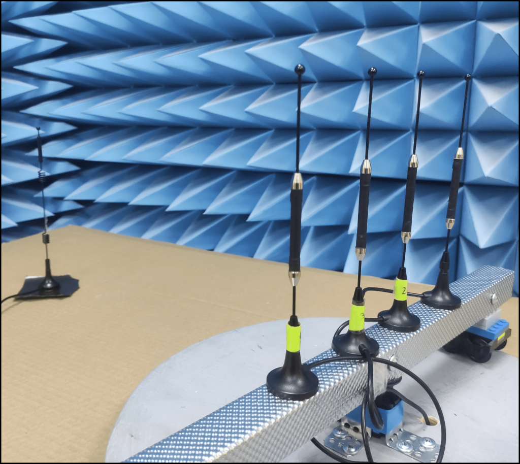
We also carry out the same experiments in an anechoic chamber. Data from such experiments is placed in the “chamber/position_N/repeat_K/angle_A” directory, where N, K, A are the same as in the previous case.
Data for calibration
The calibration process is essential for accurate angle of arrival estimation. For that purpose, we propose the same approach as in this paper, but in an anechoic chamber in order to reduce the multipath influence. We place a transmitting antenna exactly in the middle between the two receiving antennas and then capture several frames. CSI and time-domain IQ samples from such frames are provided in the “calibration/position_N/channel_С” directory, where N is a number of positions in an anechoic chamber and С indicates that receiving antennas are 1st and С-th. File “csi.mat” contains matrix “csi” with shape 242x2x30, where 242 is subcarriers number, 2 is channels number, 30 is frames number, while file “samples.mat” contains matrix “samples” with shape 1000x2x30, where the only difference is that 1000 is number of time-domain samples. Slices “csi(:,1,:)” and “samples(:,1,:)” refer to the 1st antennas, while slices “csi(:,2,:)” and “samples(:,2,:)” refer to the С-th one. Using this data, it is possible to eliminate constant phase shift between receiving channels and then perform more accurate angle of arrival estimation.
We are grateful to the Department of Radiophysics and Technical Cybernetics and personally to Igor Vladimirovich Zimin for providing us with access to the anechoic chamber for conducting experiments.
In case of using our dataset, please cite it as stated here.